project goal:
to create a power tool through a research intensive project, intended to be used during the refinement phase in prosthesis making. the power tool must also adhere to the design aesthetics of my selected brand. this tool must also be cordless and compact rotary tool, that is durable, capable of sanding at 90° angles, and has ergonomic grip that allows for more freedom of movement for the prosthetist.
summer studio 2025
duration: thirteen weeks
meet rob.
to begin the process of designing a power tool, I had to find a problem for my power tool to solve. I was originally interested in looking into different professions in the medical field that use power tools, and came across prosthesis making.
I met with rob pinkston, a 54 year old local prosthetist and the owner of Superior Prosthetic Solutions, located in Newport, Kentucky. he graduated from Bowling Green State University in 1993 with a degree in Sports Medicine.
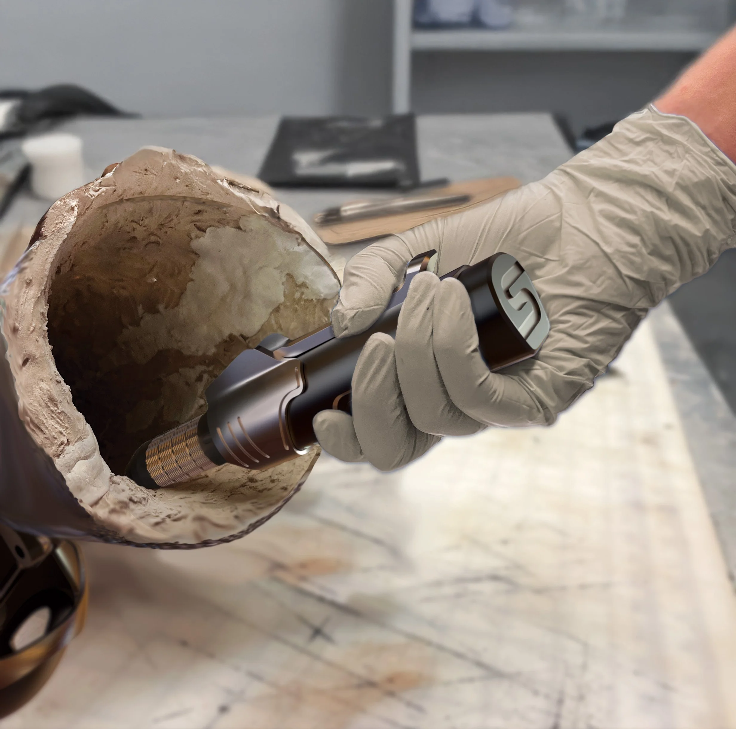
rob works independently, overseeing every stage of the prosthesis-making process. he shared that one of the most challenging aspects of his work is refining the prosthesis for the patient. during the refinement process, he uses a rotary tool to sand unwanted materials from the socket.
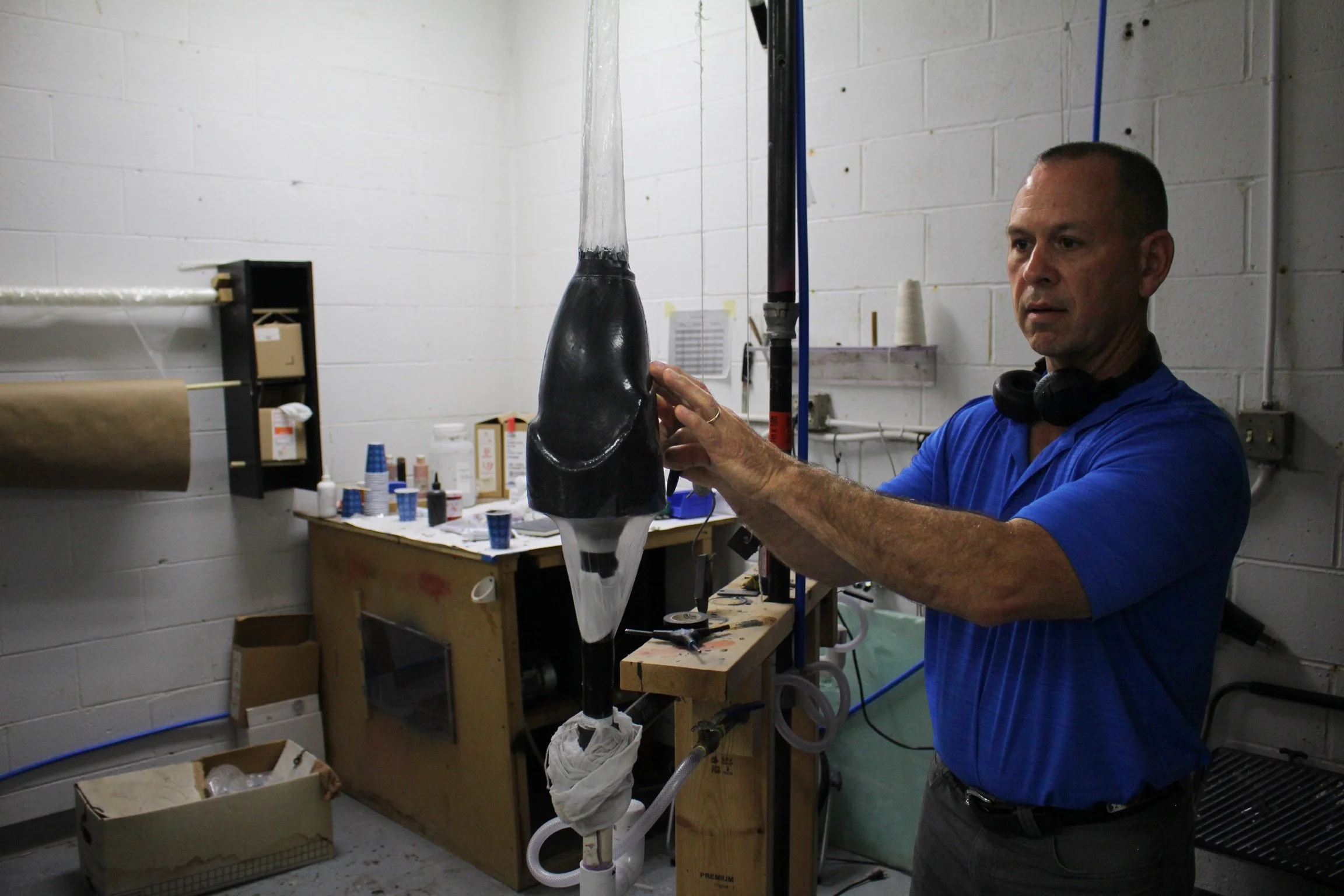
rob pinkston
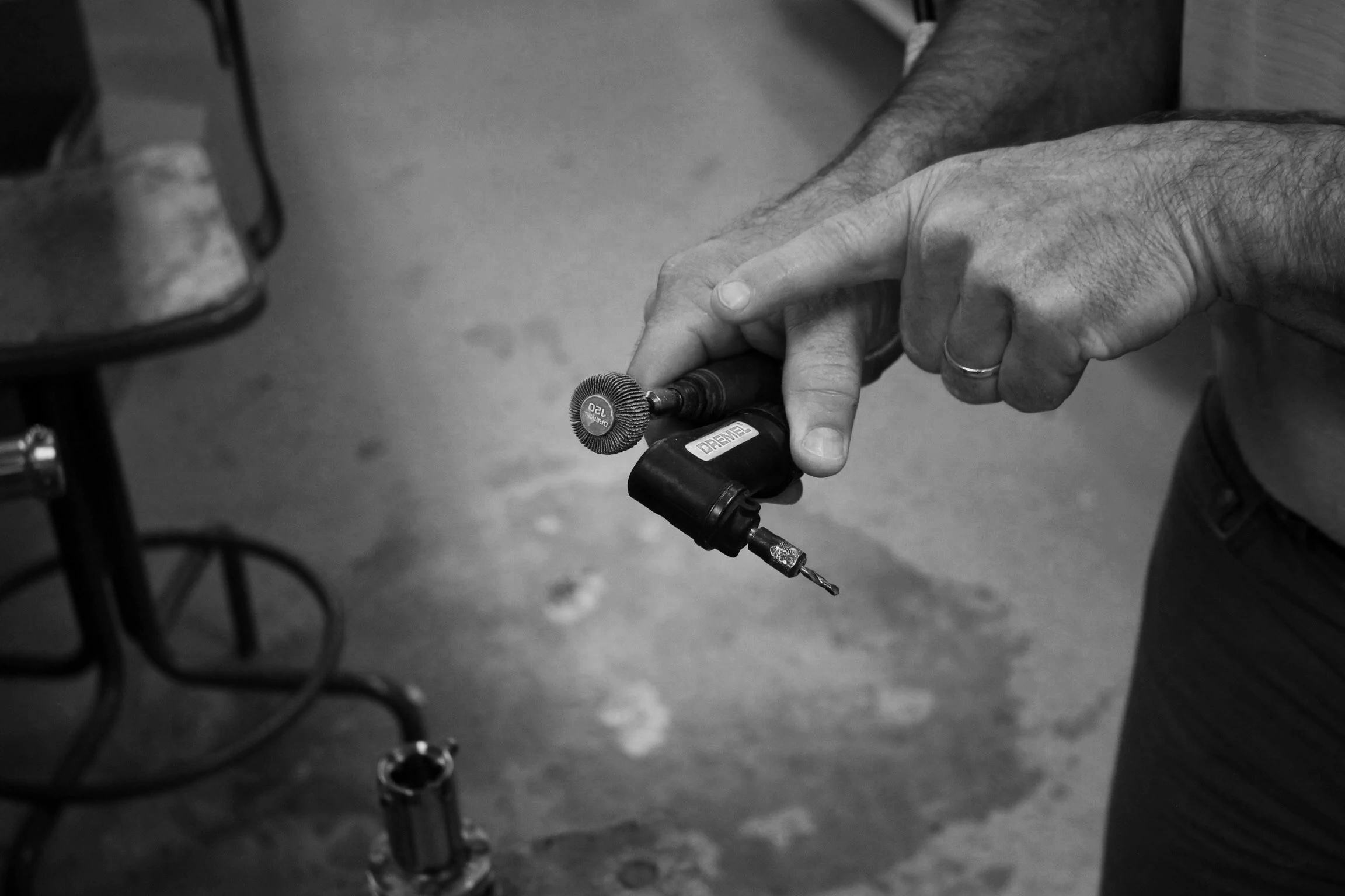
pain points of rotary tool.
tool is too large and cannot fit into the tightest parts of the socket
attachment for sanding at 90° angle is too large
no designated storage for tool and attachments
inconvenient speed adjustment and corded device creates workspace constraints
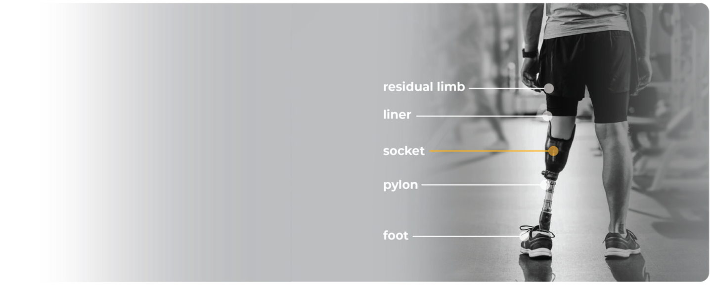
anatomy of a prosthesis.
before I began diving into the problems with rotary tools in the prosthesis field, I wanted understand to understand what a prosthesis was. I asked rob about the parts of a prosthesis and created a graphic below based on his answers.
understanding how prosthesis are made.
to understand problems that rob might run into during the refinement phase, I first did a deep dive into the actual process of creating a prosthetic limb. after gaining more insight from rob and doing further research, I have summarized the prosthesis making process into three phases:
phase one: creating the mold
creating the negative mold for the socket
phase two: creating the socket
vacuum-forming carbon fiber to the negative mold
phase three: refinement
sanding and cutting the socket to enhance comfort for the patient
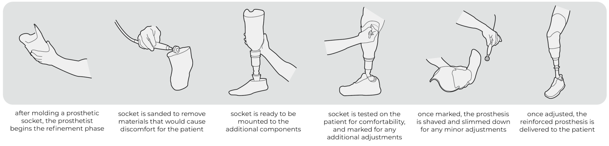
my power tool assists in the refinement phase of prosthesis creation. below is a task analysis that explains the refinement phase:
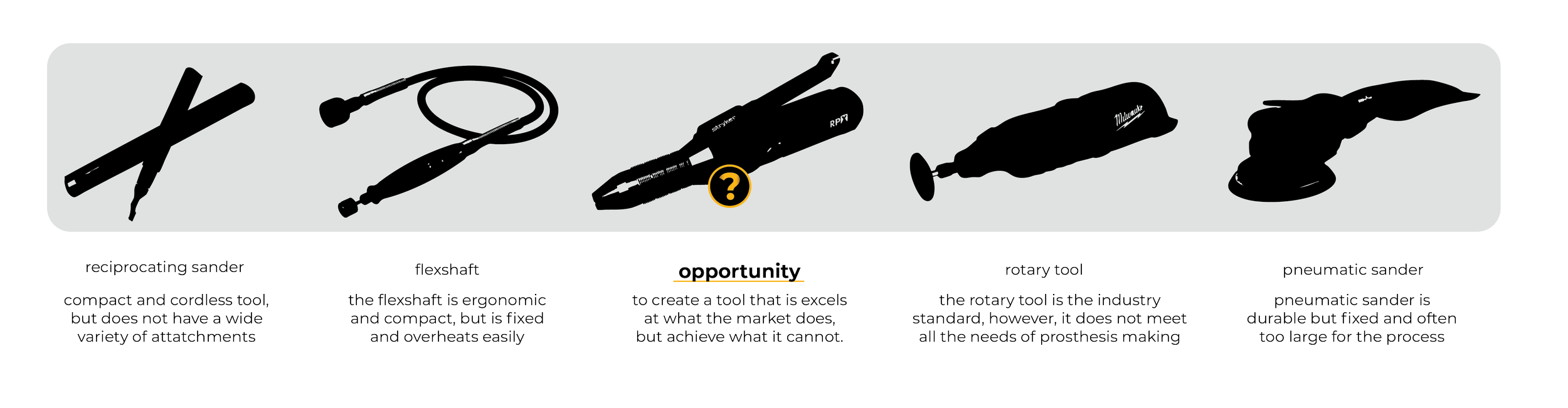
evaluating current market solutions.
to understand the current market solutions, I created an analysis on all the possible options. afterwards, I created a final conclusion graphic (seen below) of all the current market solutions for prosthesis refinement.
design goals.
to design a power tool for the specific use of removing unwanted materials from a prosthetic socket.
design objectives.
to design cordless and compact rotary tool, that is durable, capable of sanding at 90° angles, and has ergonomic grip that allows for more freedom of movement for the prosthetist. this should also include a designated place for the tool and any attachments to be stored.
assigning a brand.
after discovering the opportunity areas that I could explore with my tool, I pivoted to researching a brand to assign to my tool. before beginning to sketch initial form ideas, I wanted to have a brand in mind so I could sketch ideas that reflect their identity.
I began by doing a brand analysis of two medical device companies that create power tools, Stryker and Propio. after looking into their portfolios closely, I decided on choosing Stryker.
Stryker prioritizes workflow simplicity and making tools that have intuitive motion. I started a brand analysis by looking into their brand identity.

diving in.
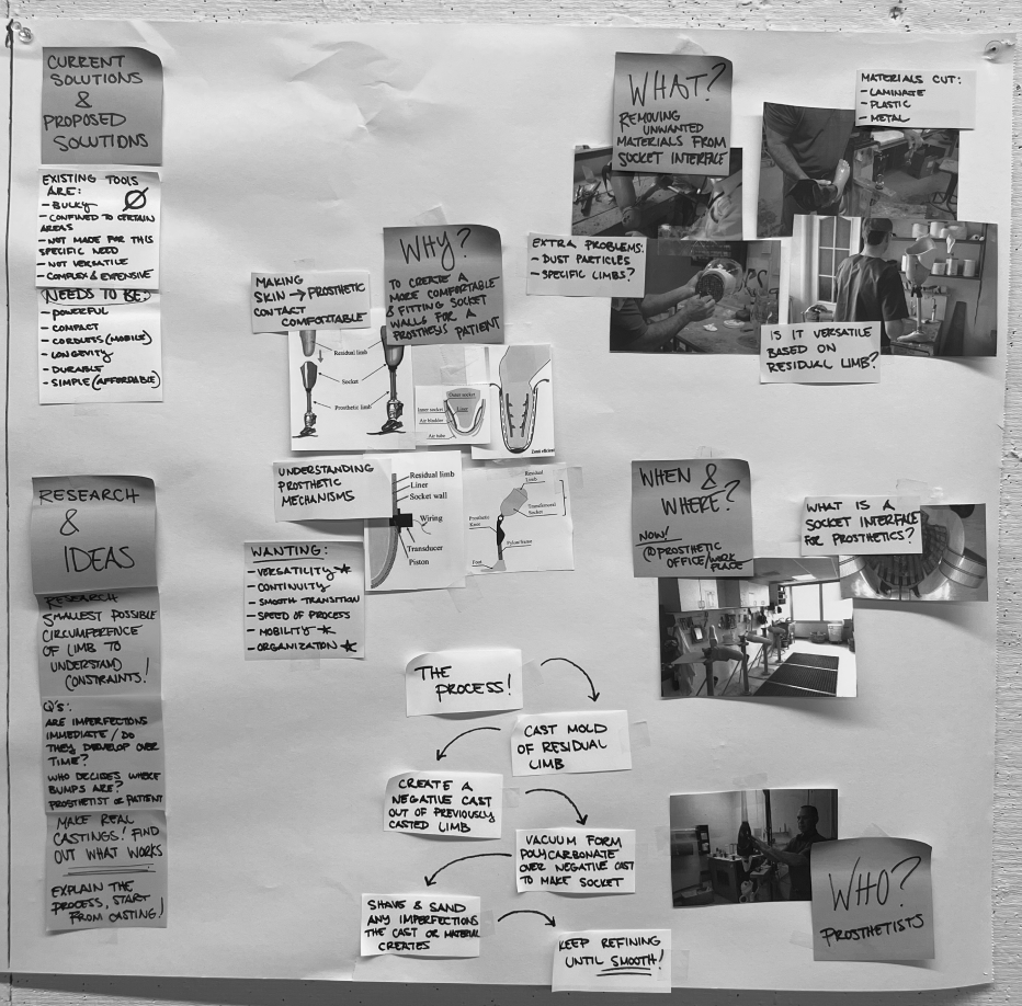
mind mapping:
to begin the daunting process of designing a power tool, I started by laying out all my thoughts and ideas on paper. I wanted to understand the “who, what, when, where, and why” of my power tool. I wanted to gain a solid foundation of understanding for my tool.
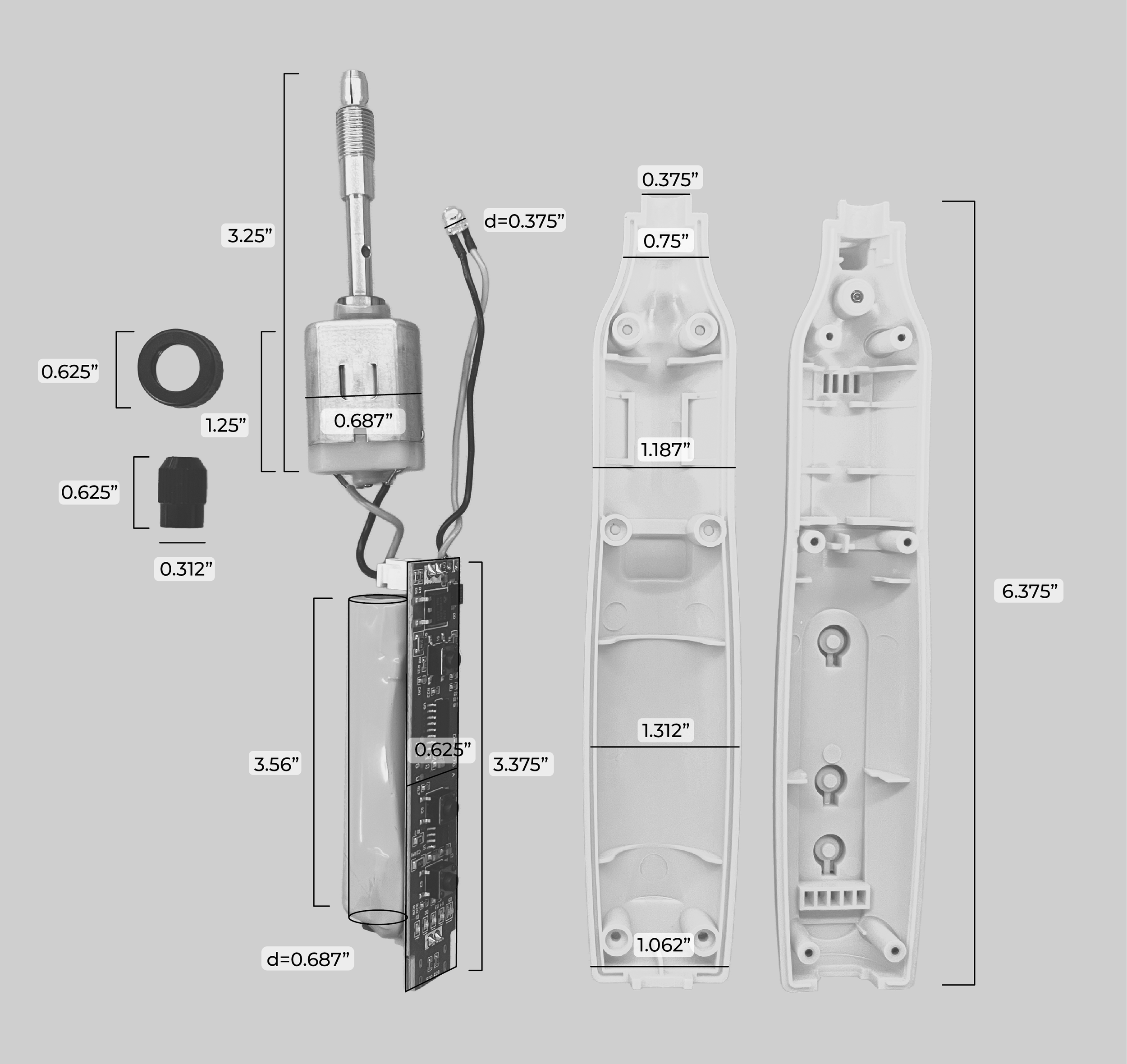
product teardown:
after mind mapping, I went out and purchased a standard rotary tool so I can understand the internals of the tool. once the tool was taken apart, I measured the parts so I could base my design around the current product’s scale.
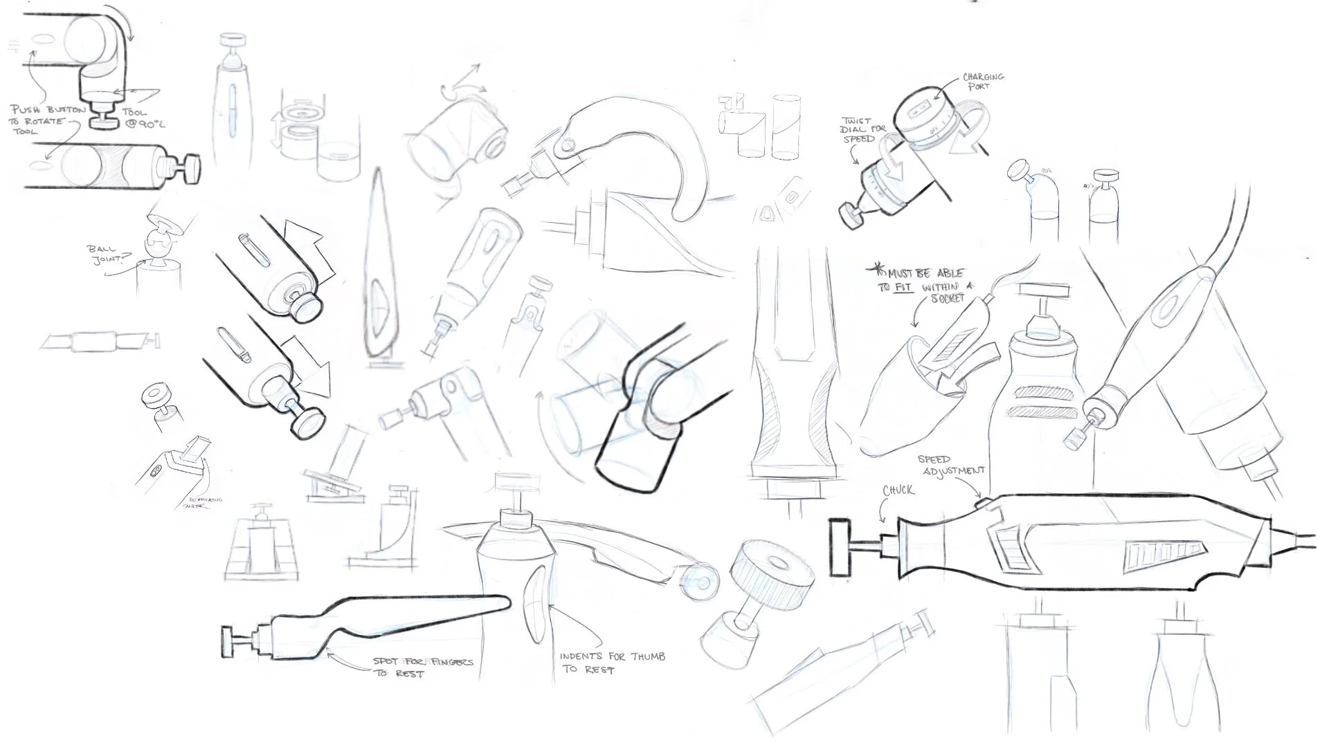
low-fidelity modeling.
after creating a round of iteration sketches, I selected my favorite concepts and created low fidelity models of them. to do this, I started by creating orthographic sketches and using the cabriole method to create foam models. after making the models, I analyzed them to see which forms i wanted to experiment further with.
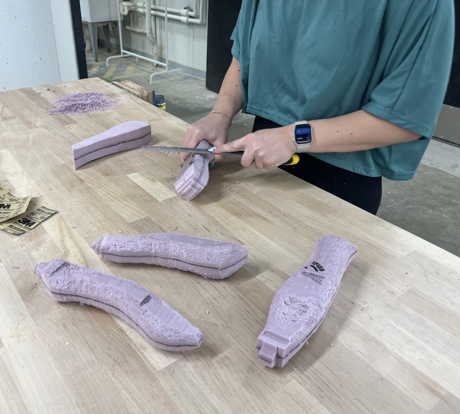
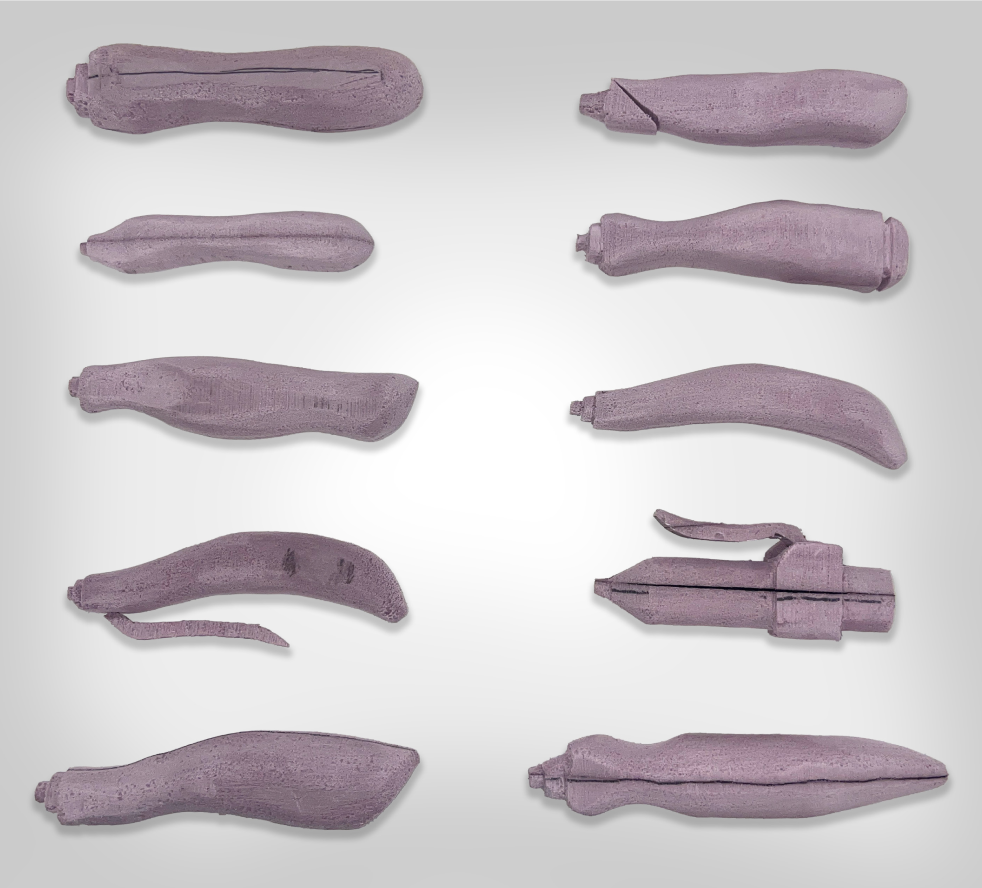
foam prototypes:
after creating multiple foam models I brought them to my peers and mentors to receive feedback on them. I wanted to make sure each of my foam models targeted a specific aspect of my DGO, and wanted to create a breadth of models so I knew which aspects were successful, and which ones were not.
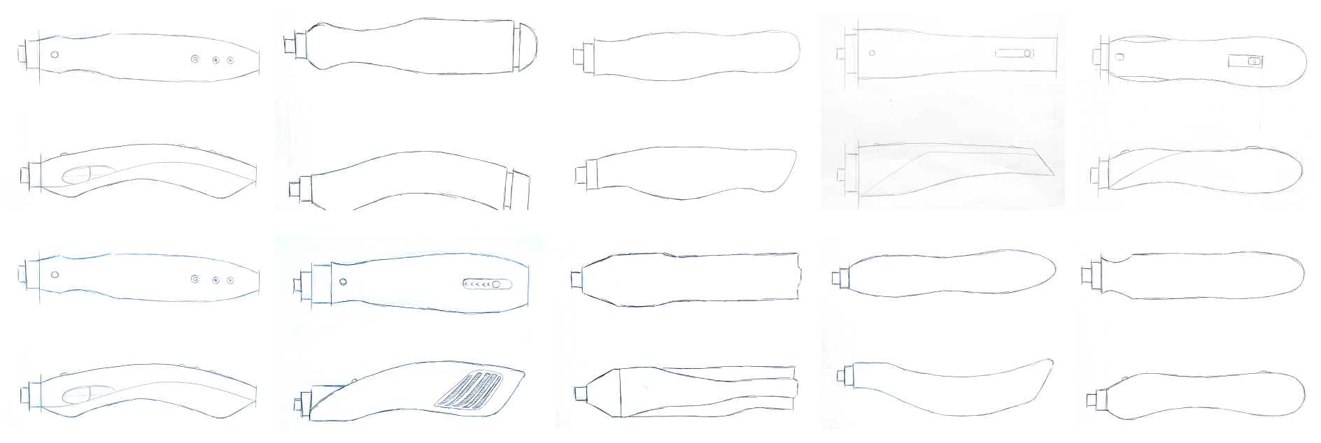
cabriole method:
to create the foam models of my tool, I used the cabriole technique. to do the cabriole technique, I start by creating a top view and side view orthographic sketches. I then placed the sketches onto a block of foam and used a band saw to cut both sides, leaving behind a full foam model.
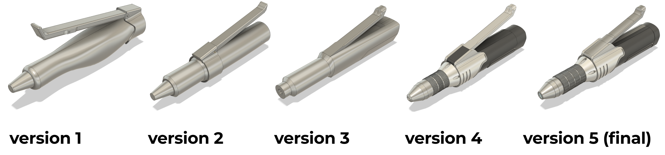
CAD modeling.
after exploring different versions of my tool’s form with foam, I moved into CAD modeling. I went through five different iterations for my tool form. throughout each version, I took notes of what was not successful, and made sure to improve that within the next model.
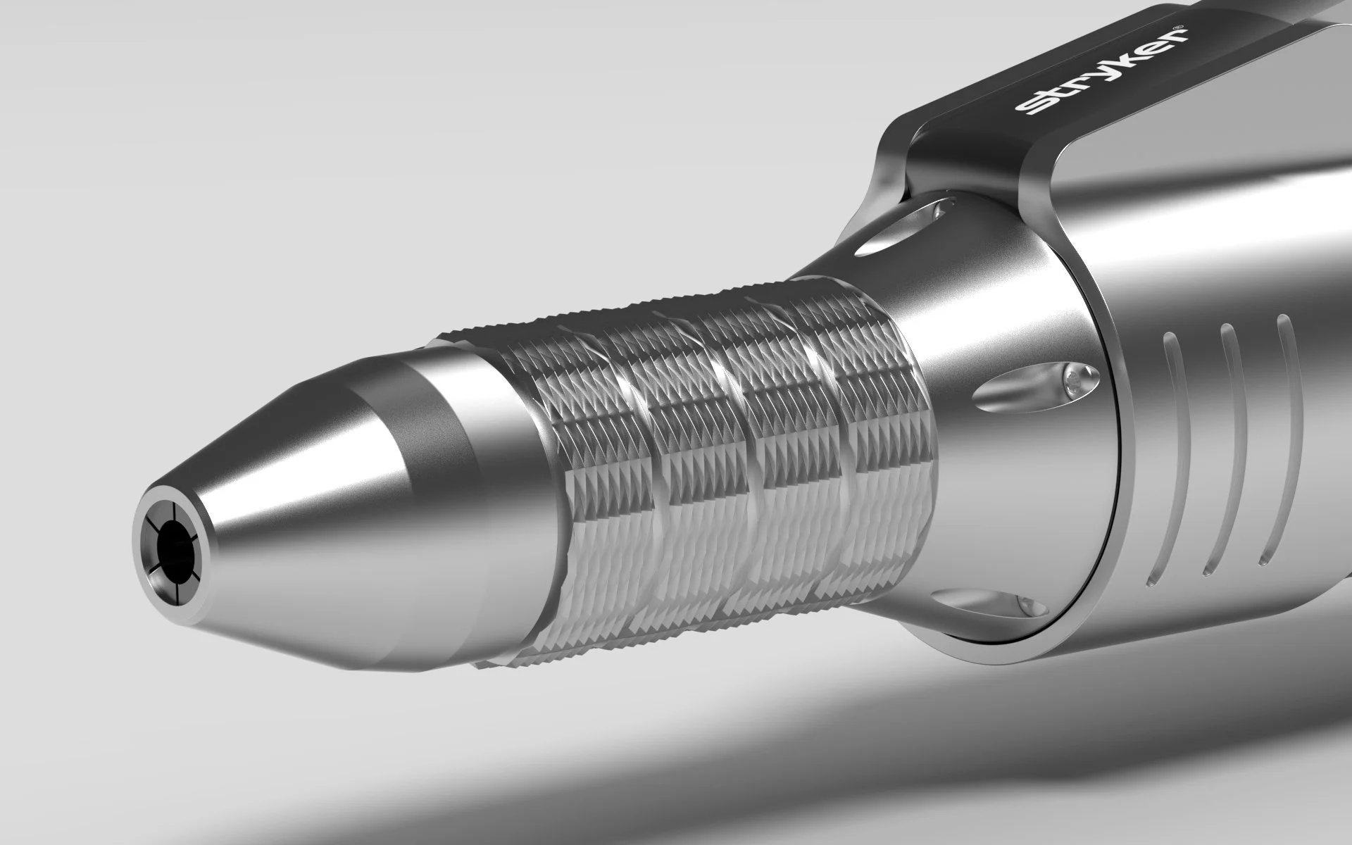
the bits.
one of the pain points that rob mentioned about his rotary tool is that the bit attachments that he uses are too large. when I was finished modeling the internals of my tool, I began to model some bits that would be useful for the prosthesis refinement phase.
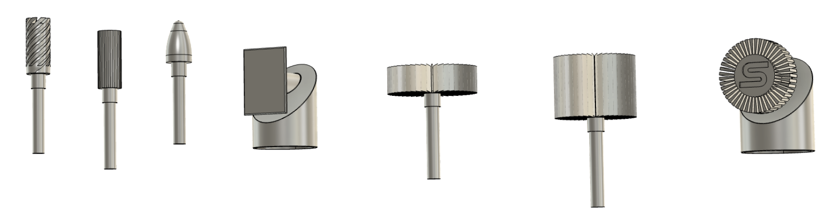
grinding bits.
I created three different steel grinding bits to target the harder and larger materials within a prosthesis socket.
oscillating bit.
I created three different steel grinding bits to target the harder and larger materials within a prosthesis socket.
flap sanding bits.
I created three different steel grinding bits to target the harder and larger materials within a prosthesis socket.
90° flap sanding bit.
I created three different steel grinding bits to target the harder and larger materials within a prosthesis socket.
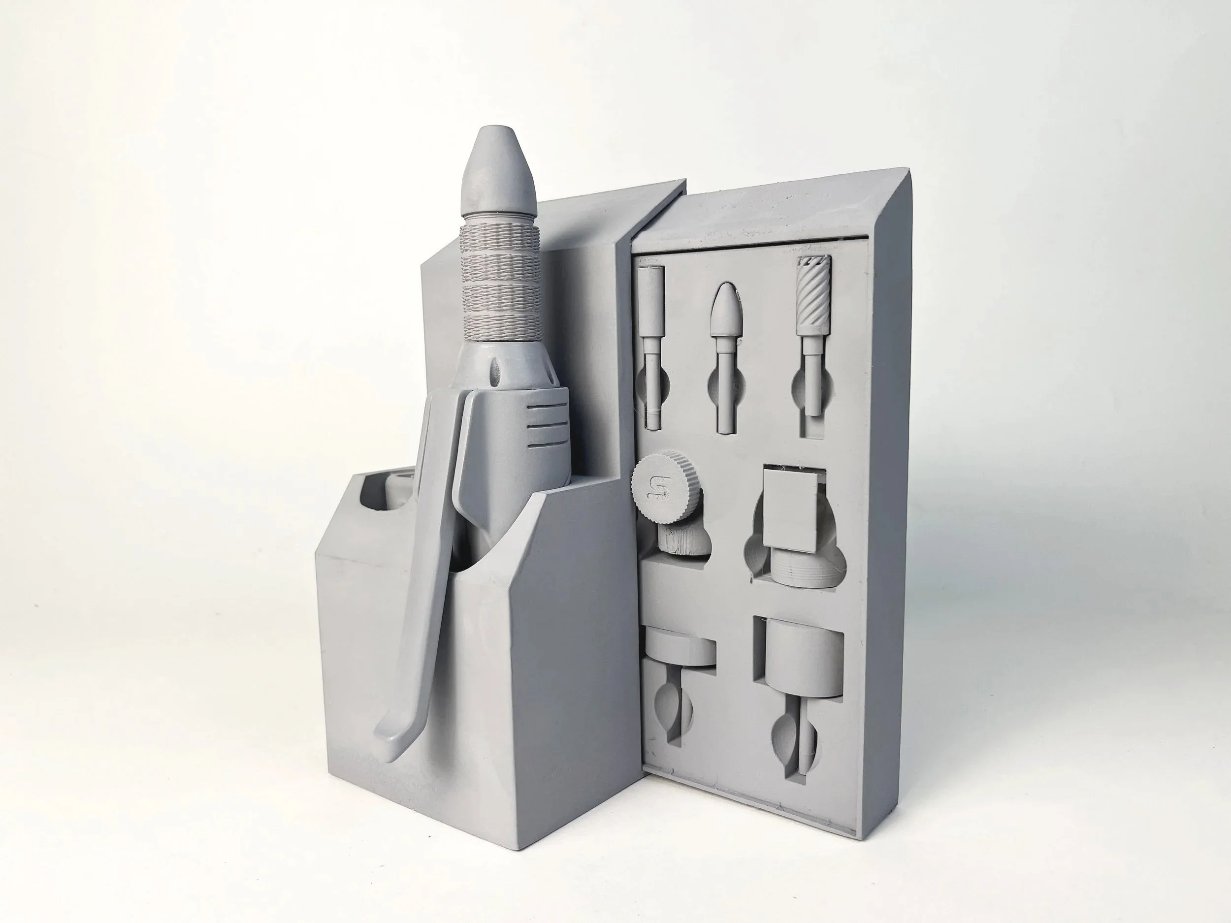
the stand.
one of the pain points that rob mentioned about his rotary tool is that he did not have anywhere to store it. when I was finished modeling the internals of my tool, I began to model a stand that would not only provide storage for the tool, but also provided housing for the bits and a place to charge the battery.
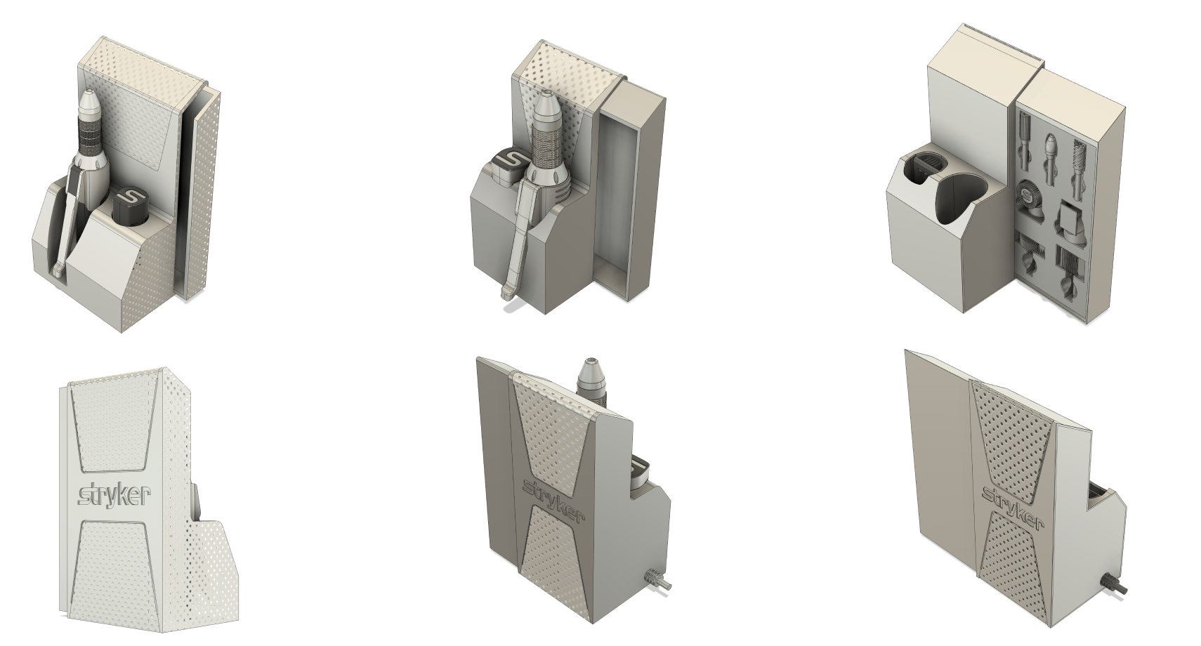
designated storage
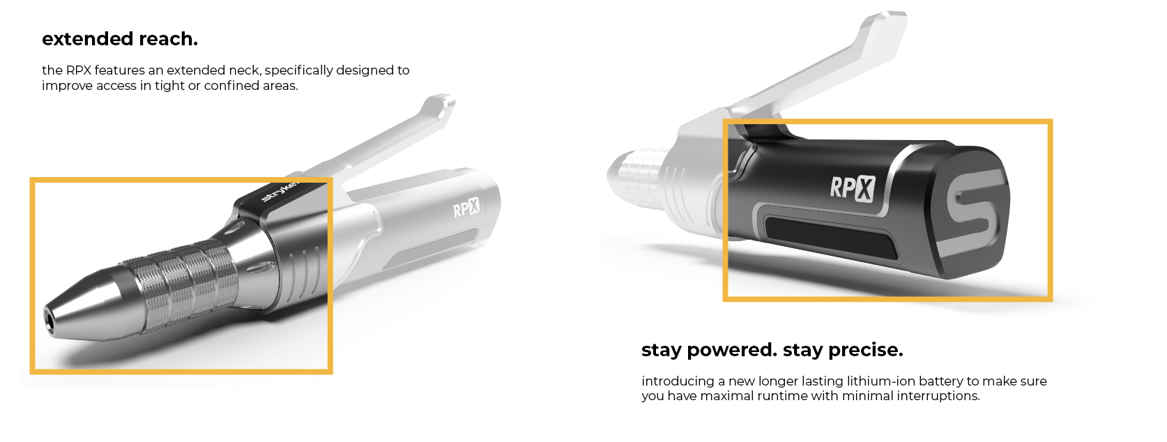
the stand features an integrated docking station that charges the lithium-ion batteries while the tool is stored.
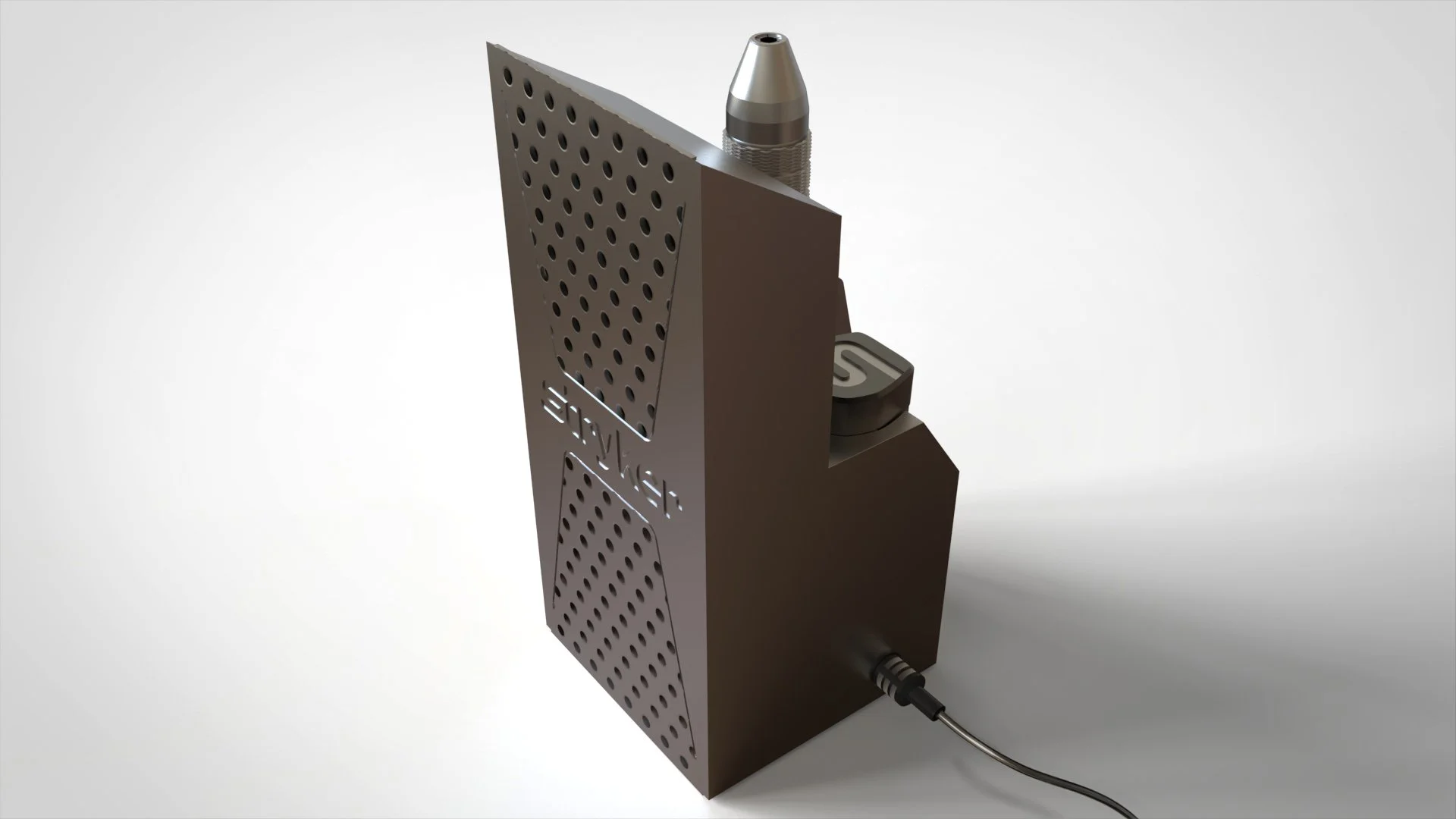
battery charging station
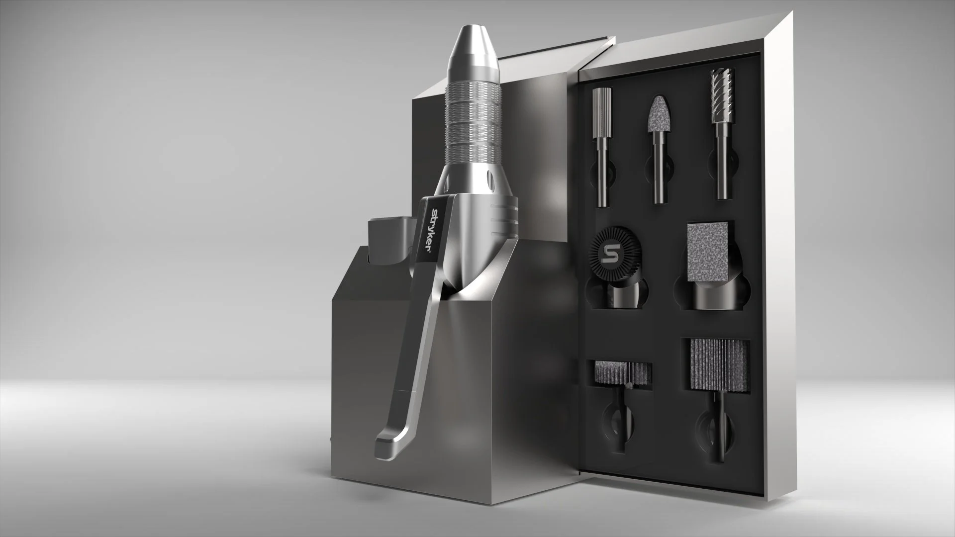
this stand provides a designated place to store the RPX when not in use, including built-in housing for all interchangeable bits. a cord on the left side can be plugged into any electrical outlet.
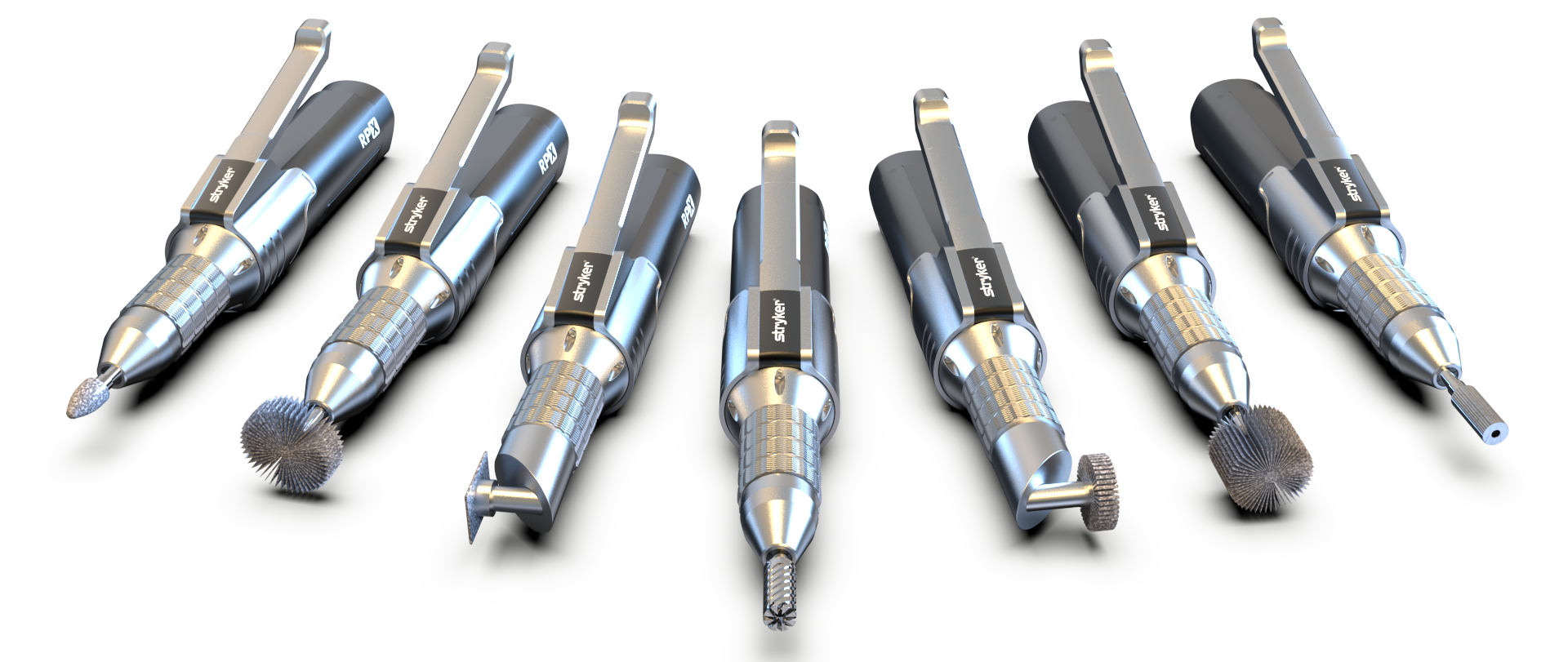
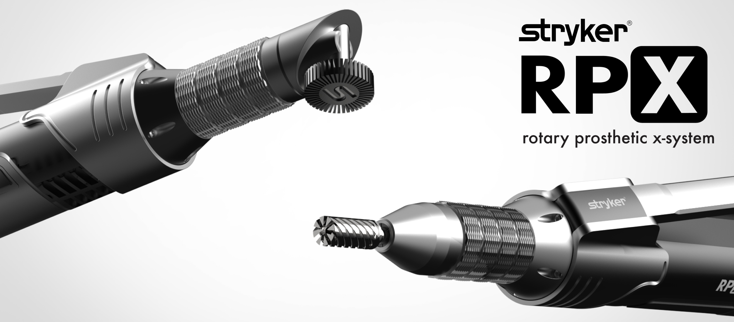
interchangeable bits
the interchangeable bit system lets the user remove material from any angle. seamlessly swap bits for any level of the refinement phase.
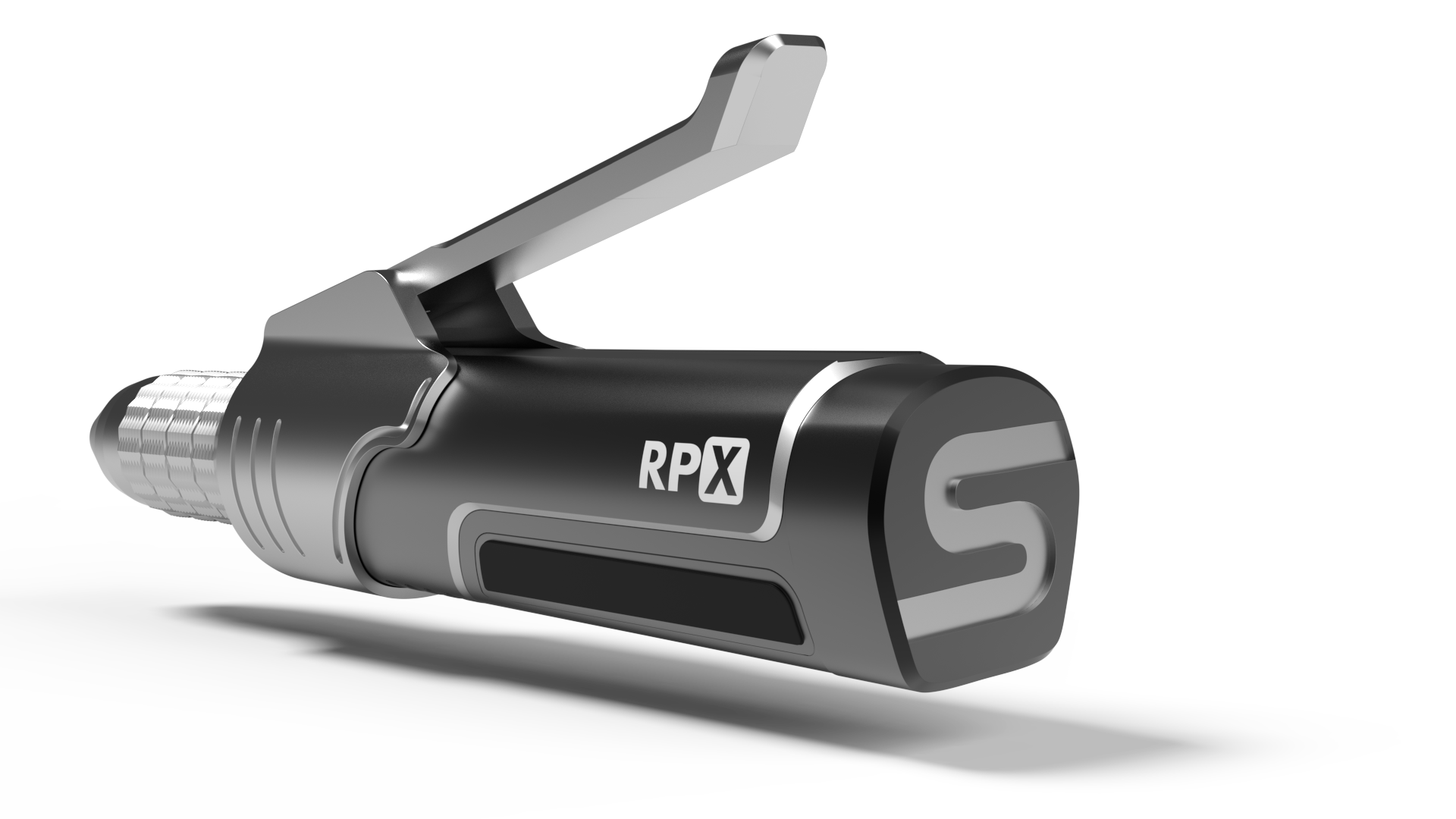
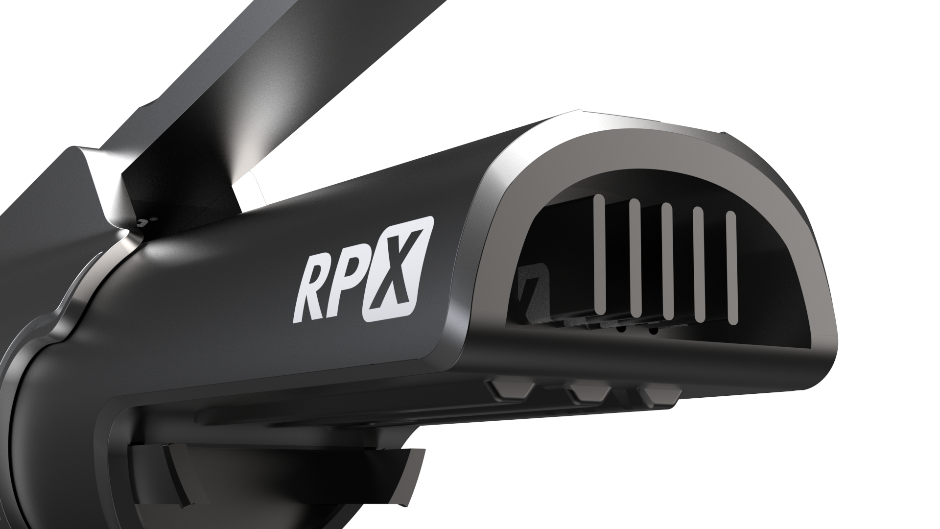
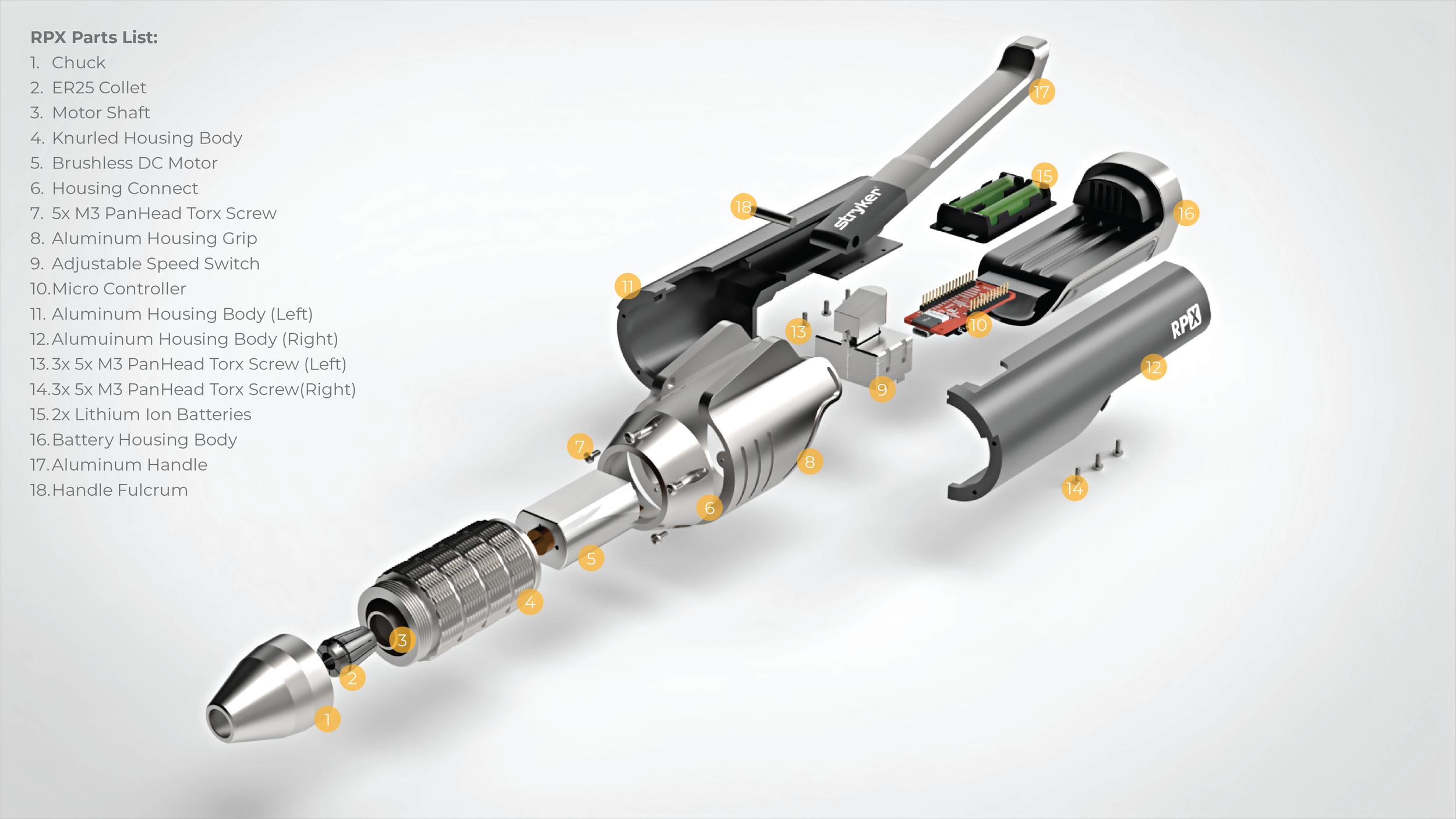
RPX parts list.
collet, torx screws, micro controller, & battery housing all resourced from GrabCAD
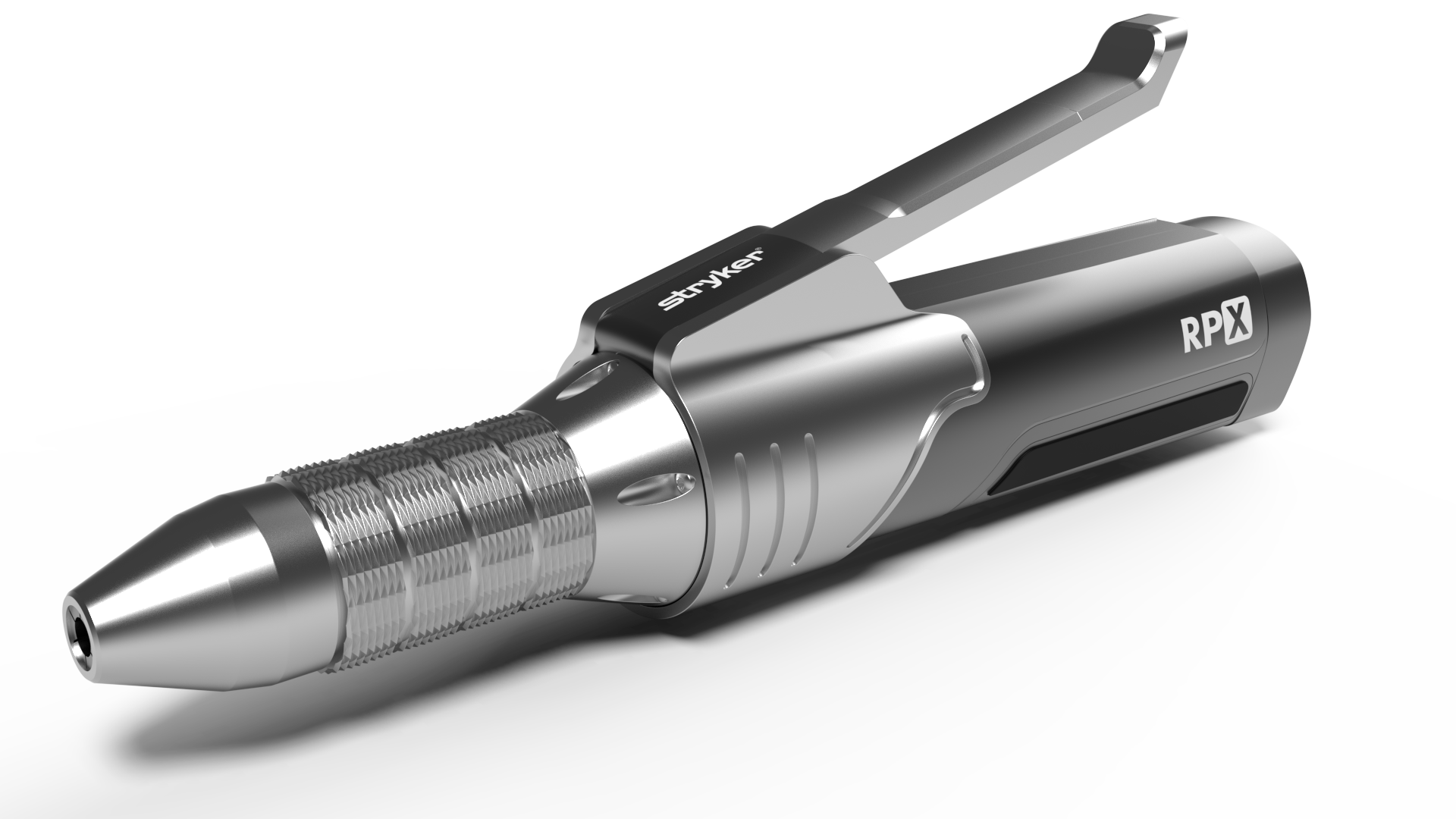
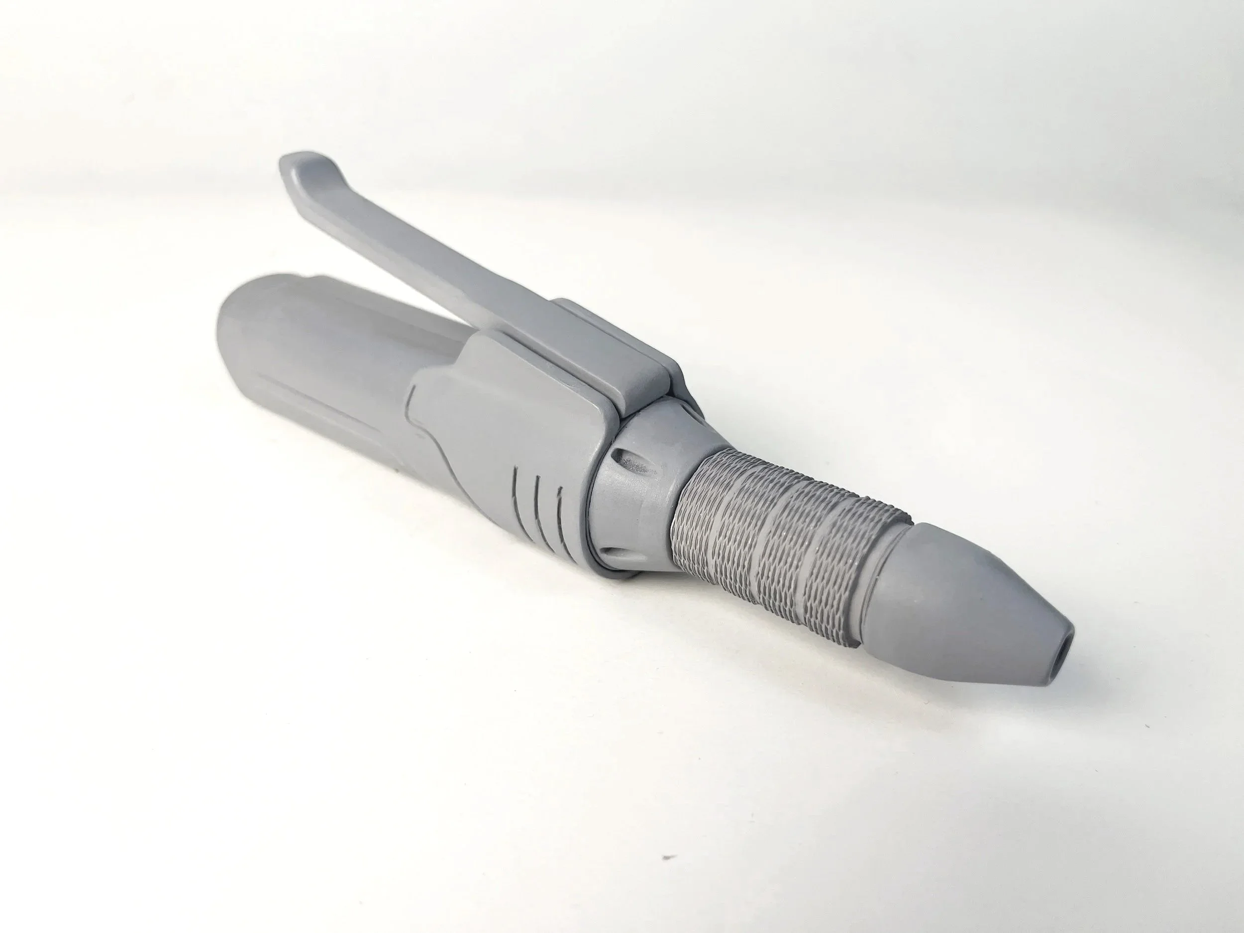
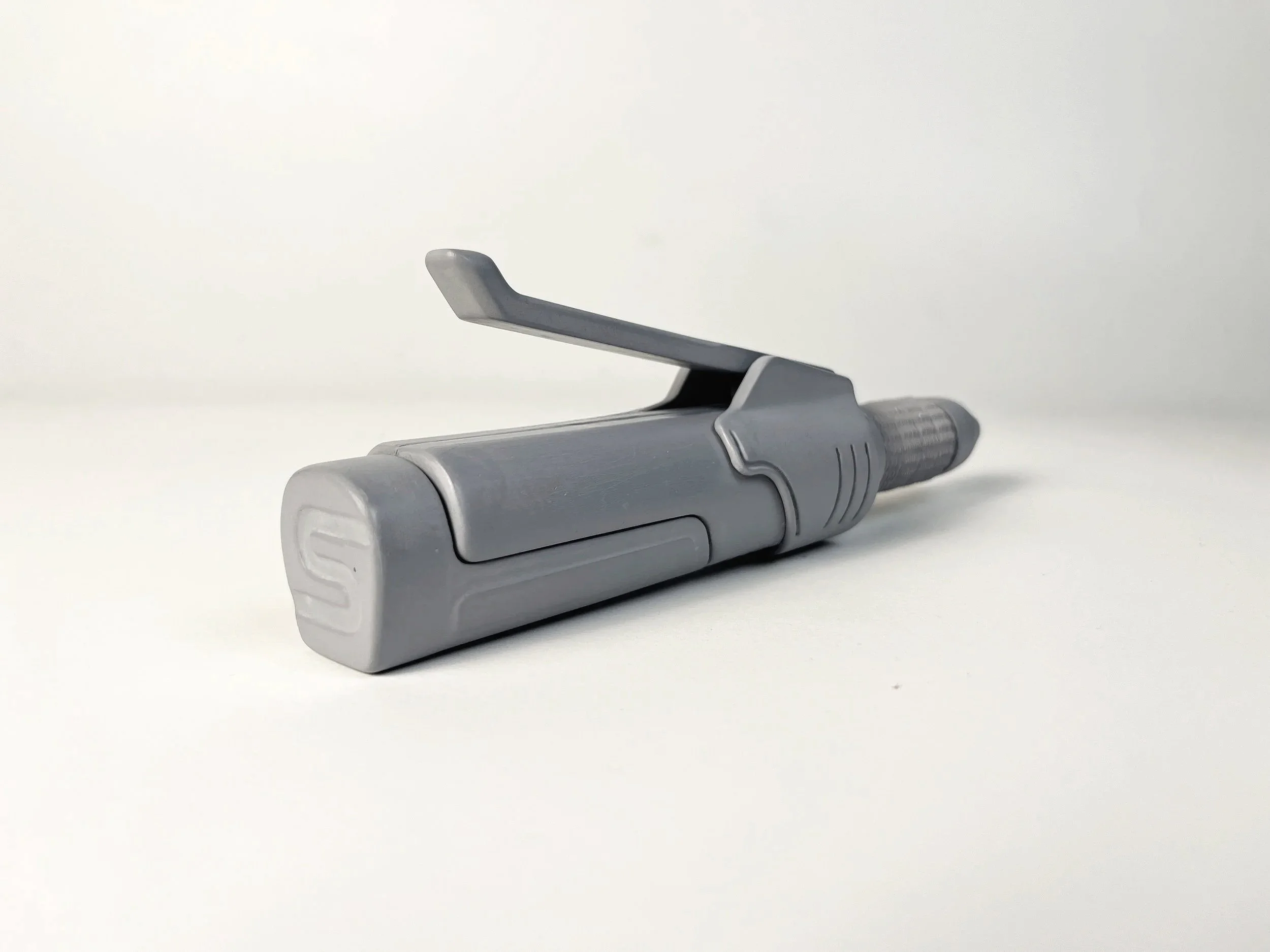
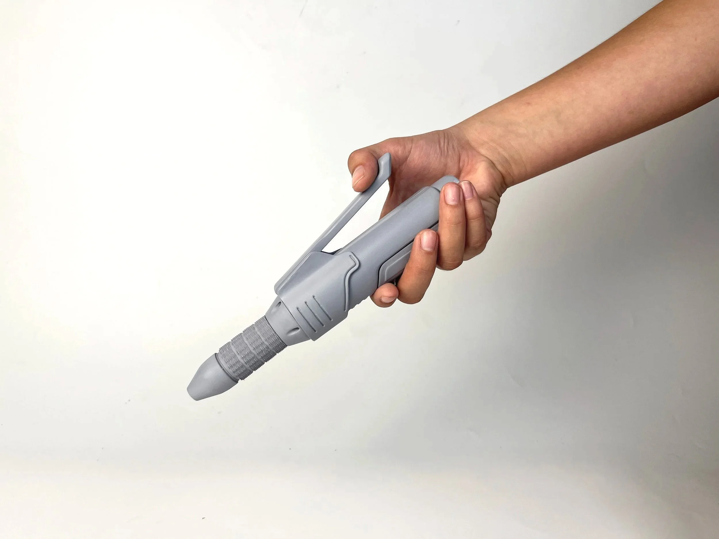
final gray model prototype.
final CAD renders.